|
The Optimised non-destructive post-fitted foam sandwich insert
Article published in JEC newspaper, spring 2007
Authors:
Håkan Johansson, M.Sc., CEO, Composult Composite Consulting AB, SWE
Petter Sjödin, M.Sc., Composult Composite Consulting AB, SWE
Abstract
One of the biggest difficulties in the sandwich industries today is load introduction.
It is very important that the insert has a well-designed load carrying geometry to ensure
the strength of the load introduction and the sandwich structure. By using this new non-destructive
post-fitted insert system with an optimised geometry for load introductions in sandwich structures
you are able to cut manufacturing costs, minimise weight and simplify design.
Introduction
Sandwich face sheets are getting thinner and thinner and the core material is getting less dense in
order to optimise sandwich structures. This is a result of industrial demands to be more cost efficient
and environmental friendly. More effective production methods, less expensive materials and better load
introduction solutions are important issues when developing more economical lightweight sandwich structures,
which fully compete with conventional construction techniques. Considering the amount of load introductions
in a sandwich construction today, there is much to gain by increasing the performance and lowering the weight
of inserts. By increasing the strength of inserts the amount of load introductions can be reduced and thereby
severe manufacturing cost can be saved.
Background
When applying high local loads through an insert in a sandwich structure the loads have to be spread over a large
surface, because of the thin face sheets and weak core of the sandwich. Such an insert should preferably have a
decreasing rigidity in order to avoid stress concentrations. Local stress concentrations in bi-material edges
often initiate failures. Well-designed optimised lightweight sandwich structures are often penalised with added
weight when the load introductions require higher density core/thicker face sheets or larger inserts.
Shipsha, Söderlund and Zenkert presented a paper on optimised internal metal doubler (IMD) for load introduction
in sandwich panels at the 4th International Conference on Sandwich Construction [1]. They performed Finite Element
analyses and shape optimisation of a pre-fitted IMD, which resulted in an optimised insert geometry. The optimisation
was performed to obtain a more even stress distribution in the core and to minimise the weight of the IMD for a
transverse tension loading. The initial design of the optimisation was a standard axi-symmetric cylindrical IMD.
Shipsha, Söderlund and Zenkert showed that by changing the insert geometry a more even distributed stress along the
IMD surface can be obtained and by that a higher predicted failure load. Figure 1b shows a standard cylindrical IMD
and Figure 1a the optimised IMD geometry with the same weight but with reduced stress concentrations.
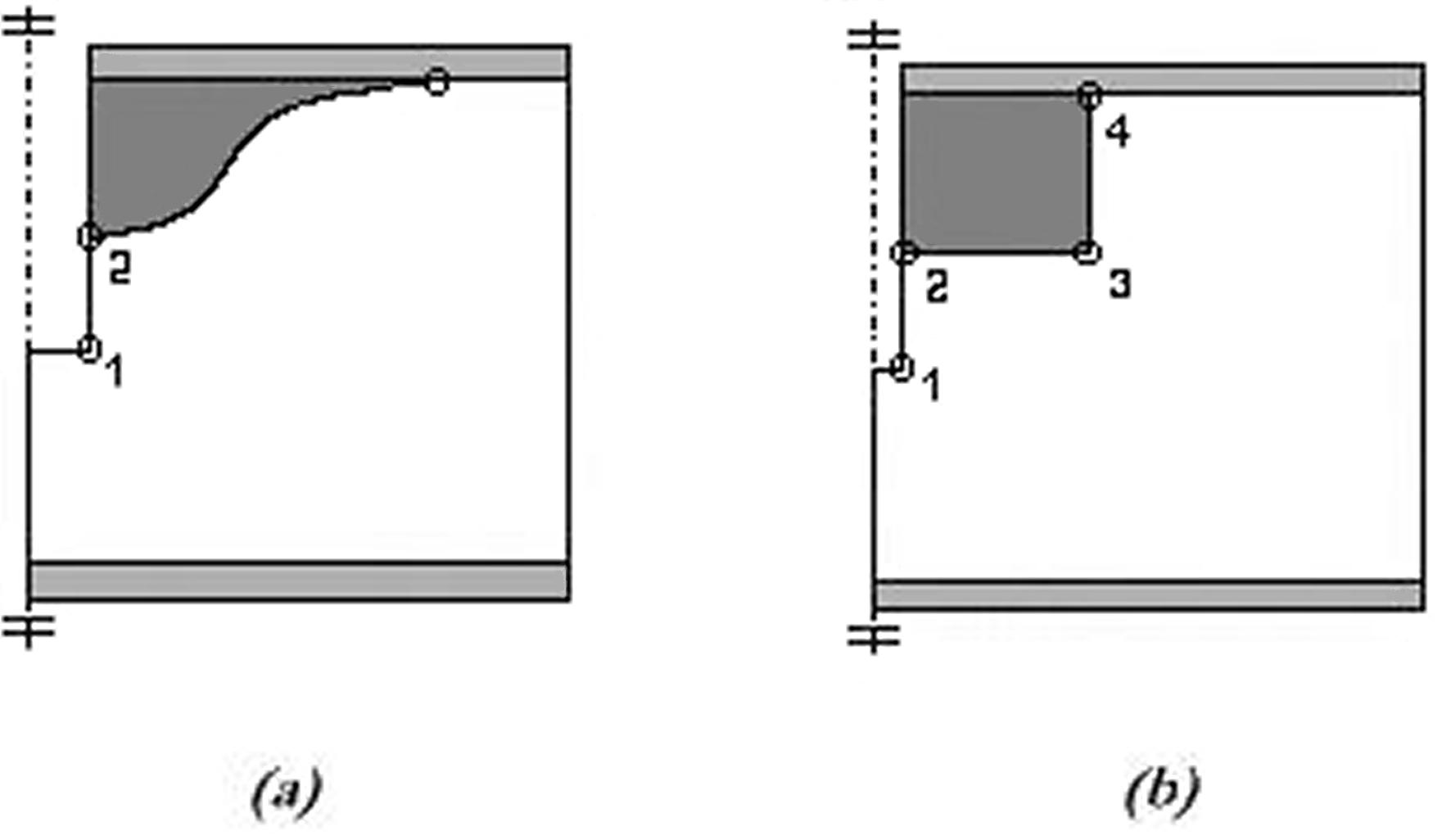
Figure 1. Models of sandwich panels containing IMD, Singular points are marked with circles [1].
(a) Optimised design. (b) Cylindrical design.
Shipsha, Söderlund and Zenkert performed analysis for a 60 mm PVC foam (Divinycell H100) sandwich panel with 4 mm
thick glass fibre reinforced face sheets. The initial and optimised design was also experimentally tested in transverse
tension to obtain the fracture loads. The results are summarised in Table 1. The predicted failure load for the
optimised IMD was three times higher than for the cylindrically shaped IMD and the experimental failure load was
two times higher. The failure initiated at the predicted singular point 3 for the cylindrical IMD (Figure 1b)
and at the singular point 2 for the optimised IMD (Figure 1a).
|
Predicted failure load [kN] |
Experimental failure load (average) [kN] |
| Cylindrical design |
7.1 |
10.0 |
| Optimised design |
20.0 |
20.6 |
Table 1. Critical loads from predictions and experiments [1].
Load introductions shaped like Shipsha, Söderlund and Zenkert´s IMD, can be both pre- and post-fitted.
A disadvantage of pre-fitted load introductions is that it makes it necessary to predetermine the locations of all
fastenings before the sandwich panel is assembled, which is very time-consuming during design and manufacturing.
Nor are the intended locations of fastenings always known before the sandwich structures are used.
A post-fitted insert is implemented in the core after assembling of a sandwich. The core cavity is normally made
with an ordinary milling tool. However, such a milling tool cannot create an optimised shaped cavity in a sandwich
structure with an entry hole in the face sheet, which is smaller than the cavity. A normal milling tool therefore
needs to be used before the sandwich structure is assembled. Using such a tool on an assembled sandwich panel
requires replacing or repairing of the face sheet. This procedure is labour intense and may result in a weaker
sandwich structure and an uneven surface.
Development
In order to simplify manufacturing and making a post-fitted insert stronger, a development project was started in 2001.
The objective of the project was to develop an economical non-destructive system to post fit a insert with an optimised
geometry. To be able to enlarge the portfolio, support different sizes of optimised inserts and reach a bigger market
the project will also continue seeking a partner.
Shipsha, Söderlund and Zenkert´s optimised geometry was the starting point for this development of a system for
optimised post-fitted inserts. According to Shipsha, Söderlund and Zenkert´s experimental testing of the optimised
IMD the failure initiated at point 2 (Figure 1a). This indicates that if the singular point can be eliminated by a
smoother transition to singular point 1, the failure load will be increased further. This modification can be done
with a small weight increase. Figure 2 shows the resulting geometry based on Shipsha, Söderlund and Zenkert´s result
with an additional smoother transition to point 1. Experimental testing of the final geometry is scheduled.
This new insert system includes a milling tool that creates a cavity with this specific geometry for post-fitted
inserts without removing the face sheet. The geometry is also well suited for through the sandwich inserts.

Figure 2. Optimised cavity created by the milling tool. (a) Optimised geometry. (b) Optimised through
the sandwich geometry. (c) Photo, resulting cavity in Divinycell H80 core, created by the milling tool.
� The milling tool
The rotating milling tool (Figure 3) [SWE pat & int. pat. pending] expands during rotation powered by the centrifugal
force. A normal power driller (3000 rpm) ensures the necessary centrifugal force, which makes it easy useable.
The cutting sheath moves along the face sheet during rotation and simultaneously cuts out the optimised cavity in
the core. This is in the end the contour of the insert. The supporting bearing plate fixates the tool during use
in axial and radial direction at an adjustable depth. The milling tool will thereby be usable for different face sheet thickness.
This tool makes it possible to mill an optimised cavity in an assembled sandwich structure. The tool only needs an entry
hole through the face sheets, which is substantially smaller than said cavity.

Figure 3. The patented milling tool. (a) CAD model with closed up cutting sheath. (b) CAD model with
partially expanded cutting sheath. (c) CAD model with fully expanded cutting sheath. (d) Photo of a prototype.
The system
The optimised post-fitted insert system consists of the milling tool, adhesive, adhesive dispenser and if needed
female/male threaded insert. The adhesive dispenser makes sure that the right amount of adhesive is filled in the
cavity. The adhesive should have a specific viscosity, which ensures that the air flows out of the cavity during
mounting of the insert. For application without very high structural demands it is possible to use only the cured
adhesive as an insert.
This system for mounting (Figure 4) an optimised non-destructive post-fitted insert is very flexible and less
labour intense than optimised post-fitted systems used today. The fact that an optimised insert can be mounted
without demounting and reassembling the face sheets with a risk of decreased structural performance as a result
makes this system beneficial. The adhesive dispenser with adjustable volume dosage for each insert size makes
the mounting repeatable, which guarantee the quality of the assembled inserts. Figure 5 shows cut-outs of sandwich
panels with mounted inserts.

Figure 4. Schematically work description of the system. (1) Foam core sandwich structure, (2) Drill
a hole through the face sheets with the same diameter as the milling tool, (3) Adjust the milling tool for the
specific face sheet thickness. Place the milling tool in the drilled hole and attach it to a power driller,
(4) Mill the cavity, (5) Clean the cavity with a vacuum cleaner, (6) Use the specific adhesive dispenser to fill
the cavity with adhesive, (7) Place the female/male threaded insert in the cavity, (8) Wait for curing. The insert
is ready for use.

Figure 5. Cut-outs of sandwich panels with mounted inserts.
References
[1] Shipsha A., Söderlund J., Zenkert D., Shape Optimisation of an Internal Metal Doubler for Load Introduction
in Sandwich Structures, Proc. Sandwich Construction 4, pp. 839-851, Emas Ltd, West Midland, UK, 1998.
| |